Adding Cornerstones and other text blocks to your structures
In the past, it was quite common for a building to have an etched cornerstone showing the date of construction, and many buildings also had header or cornice stones - a block at the top-center of the building often proclaiming it's use. This could vary from a company name to the builder/owner. These details are rarely if ever added to commercial models but are fairly trivial to add to a 3D printed structure to give it a personalized "home town" feel.
The Tools
We're going to leverage the fact that a 3D printer Slicer program can import an SVG file to print. SVG format files are widely used to create scalable images, and there are even free tools available to create and edit them. We're going to use Inkscape (https://inkscape.org/) to create our example, although you can use any tool at your disposal. Inkscape requires virtually zero design experience for this task, opening this up to modelers of any skill level.
We'll assume that you have installed a suitable design tool and have the fonts that you want to use installed.
Starting with a new page, select the Text tool. Select the font you want to use and select a size, such as 20 to 36 point. You want this to be large enough to easily read and manipulate on the screen - it will be scaled later in the slicer. For this step, we'll create a cornerstone date by typing "1090 AD". I used a typeface called "Engravers MT" because it closely resembles the typeface used on many early buildings.
I noticed that the cornerstone on my reference photo had the year slightly larger than the "AD". I set the year to 20 point and the "AD" to 16 point to make this change. Next is a critical step, changing the text to an outline drawing. Before we convert this, I usually copy the text and set it to a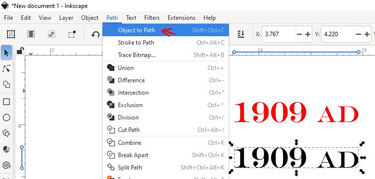 different color to allow later edits. (Inkscape: Using the Select tool, click the text, press Ctl-D, then hold the up-arrow key to move the duplicate image. Pick a color, such as Red.)
Select the first image and convert it to an outline Path. (Inkscape: Menu Path - Object to Path). You won't see any 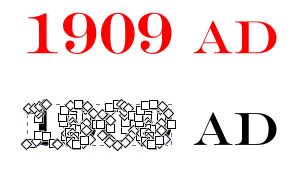 obvious change, but if you are interested, select the Node Edit tool (IMAGE) and click on your original text that you converted to a path. You will see many individual nodes that make up the text! We don't want to change anything, so return to the select tool.
Now that the text is a path, we can export it as an SVG object and move into the slicer. Select the Export tab, make sure that the text PATH is selected, and check the "Export Selected Only" button. Browse to a working folder and make sure the file type is "Plain SVG". I called my file "1909ad.svg".
Next, launch your 3D printer slicer software. I'm using the Bambu Lab slicer, so yours may look somewhat different. I loaded the wall from a background building into the slicer and gave it a brown brick color just to help it stand out for this process. 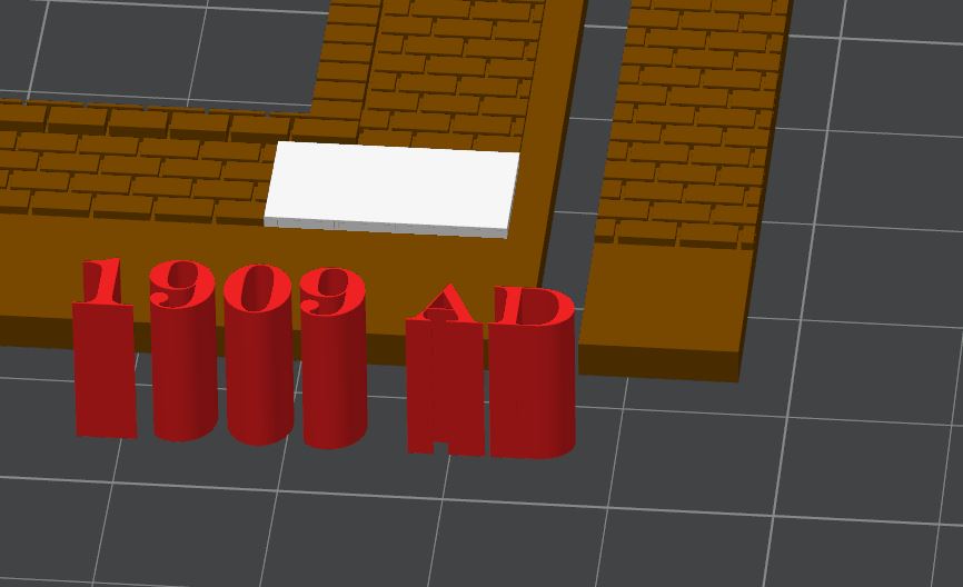 I used Drag-n-Drop to add the SVG image to the build plate, giving it a red color to make it stand out. Next, I added a cube Primitive, placing it on the wall and sizing it so that it looked like a reasonable size - about 4 bricks high and 3-4 bricks wide. I made it just thick enough so that it rose above the brick faces in that area. The white area will represent the cornerstone and making sure it looks right is the first step.
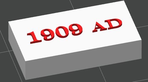
Next, we move that white cube into a separate space - it's time to add our text. I moved the wall off the plate and then centered the cube and the text on the plate. The text now needs to be scaled to fit the plate. Select the text object, select the scale tool 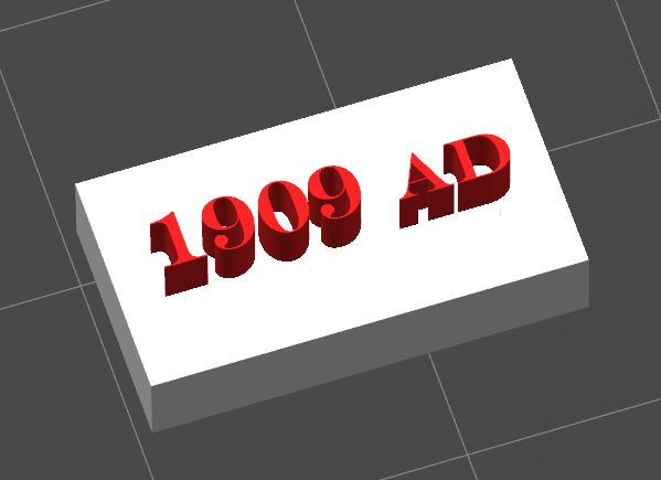 and click the "uniform scale" option. Grab one of the corner handles and move it until the text fits within the cube. Turn off Uniform Scale option and set the Z-height to 5mm. Don't worry - this will simplify the calculation later! You can see how this text sticks up above the face of the cube. Select the cube and the text, then right-click and choose Merge to assemble both objects into a single part.
Now - you have two options - either raised or inset text. Inset is more common and is engraved into the stone. We'll look at both options.
Raised Text
if you want the text to be raised:
- Select the cornerstone assembly, select the cube, and use the Scaling tool to determine its height. My example is 3.1mm.
- Decide how high the letters should be above the cornerstone. For simplicity, I am choosing 0.3mm, which is just about 1 inch in HO scale. Select the text object(s) and using the scaling tool, set the Z height to 0.3mm. They will probably disappear into the cornerstone - don't worry! we'll move them in the next step.
- We need to set the Z-axis position of the text objects to 3.1mm plus HALF the thickness of the text (0.15mm) or 3.25mm, The Z-axis represents the center of the object, so we need to raise it half its height above the height of the cube. Select the text object, then select the Position tool and manually set the Z value to 3.25. You can see from this image that the text is now just barely higher than the cube.
- Select the assembly, duplicate it (we're going to use the copy to create a block with inset text). Select one of the assemblies, right click and choose Mesh Boolean to create a single, solid object. Change the color to White if necessary
Inset Text
Inset text uses several of the same steps, except that for step 3, we're going to subtract half of the text thickness!
- Select the cornerstone assembly, select the cube, and use the Scaling tool to determine its height. My example is 3.1mm.
- Decide how deep the letters should be below the cornerstone face. For simplicity, I am choosing 0.3mm, which is just about 1 inch in HO scale. Select the text object(s) and using the scaling tool, set the Z height to 0.3mm. They will probably disappear into the cornerstone - don't worry! we'll move them in the next step.
- We need to set the Z-axis position of the text objects to 3.1mm minus HALF the thickness of the text (0.15mm) or 2.95mm,
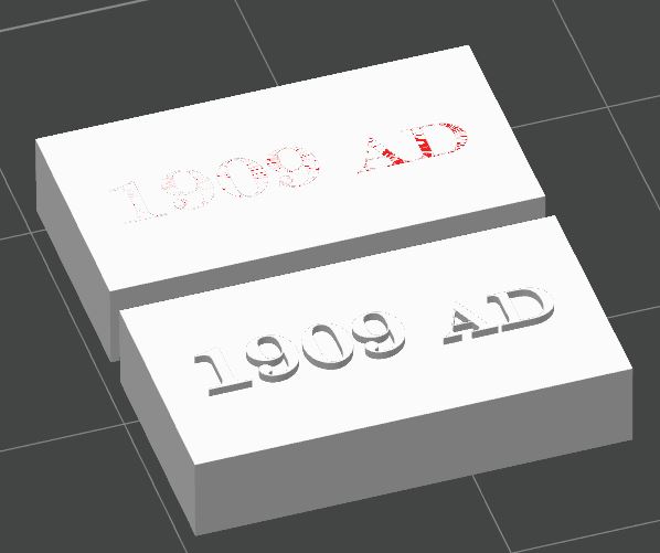 The Z-axis represents the center of the object, so we need to raise it half its height below the height of the cube. Select the text object, then select the Position tool and manually set the Z value to 2.95. You can see from this image that the text is now just barely touching the surface of the cube. The image on the left shows the inset stone on the top and the raised stone on the bottom. As you can see, it isn't easy to distinguish the different parts, which is why I like to work with different colors, even if the finished item won't print in those colors.
- This step will convert the text to negative objects, allowing an inset to be created. Select the text object from the parts list on the left side of the interface. Right-click and choose Change Type from the menu. Select "Negative Part" from the list and click OK.
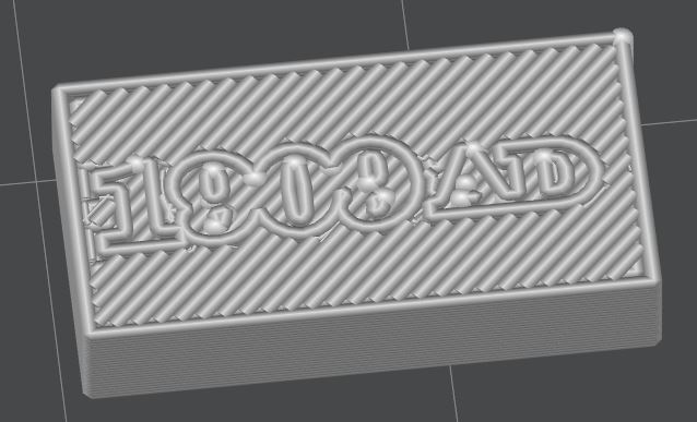
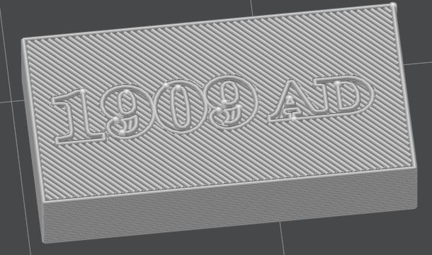
For the negative part, you must now make a configuration change that will affect the overall print. A 0.3mm thick object is just 1.5 layers at a default of 0.2mm layer height and may not provide enough definition to render this negative text, especially with a 0.4mm nozzle. You will probably want (need) to set the layer height to a smaller value to allow enough depth to the inset letters. The images below show the preview using a 0.4mm nozzle and 0.12mm layer height (left) and a 0.2mm nozzle with the same 0.12mm layer height.
Summary
Given the small size of the cornerstone and the text, having it 100% readable may not be a requirement. It's more about adding the detail. This same process can be used to create an engraved building name along the cornice or facework. These are often larger than the cornerstone, and this method will provide a very legible and easily readable result for even slightly larger text.
Here's the result of merging the cornerstone assembly into the wall and previewing the print: 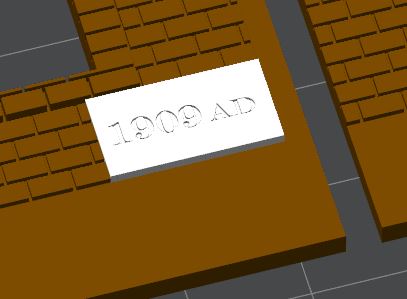
I think the result is pretty good and adds a detail rarely seen in model kits without too much effort. All that's left is to print the wall and assemble the model.
Improving print speed
After checking the preview statistics, I found that the cornerstone caused 27 filament changes. This was due to it being embedded into the entire wall, which is not necessary. There are two simple ways to fixe this.
- Before merging the wall and cornerstone, CUT (not scale) the cornerstone so it is only about 1mm thick. Then place it in position and merge it into the wall. This will reduce the number of color changes required.
- If you already merged it into the wall, you can place a Modifier cube under the cornerstone and force it to print that section in the same color as the wall.
Either of these methods reduced the number of color changes from 27 to just 9, and of course, printing in all one color and just painting the cornerstone would not require any color changes!