Electronics and Wiring
Electronics will play a big part in my layout! I will use J/MRI software to manage engine configurations and aid in programming as well as automate operations - from generating switch lists to automatically running a passenger train that operators need to be mindful of. DCC is used for train control - I've been a Digitrax user for over 22 years. A new feature in this layout is the use of LCC for control of non-train devices, including detection, signaling, turnout control, and panel automation. This integrates into J/MRI Panel Pro for simulated CTC.
 Program/Test tracks on
the Dispatch Desk
J/MRI
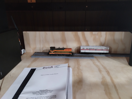
I use a tiny PC running Windows 10 that's mounted on the small dispatch desk under the layout. It's right next to the electronics cabinet, so USB connections to DCC and LCC are kept to a minimum. The PC has a 22" touch-screen monitor that's fun to use with Panel Pro. This dispatch desk has two short pieces of Kato UniTrack affixed near the backsplash. The short track is a dedicated programming track while the longer one is connected to the same power district as the engine terminal, allowing me to program and then quickly test the changes right from the same location. I may ultimately use a single long track with a toggle to switch between Program and Run actions, but this was good to get me started.
I have a dedicated network and WiFi for the train room, allowing my operators to connect, use the WiThrottle app on their phones, and have access to the Internet without any access to my home network. I have a blog article on how this can be set up.
DCC
 Overview of my DCC configuration
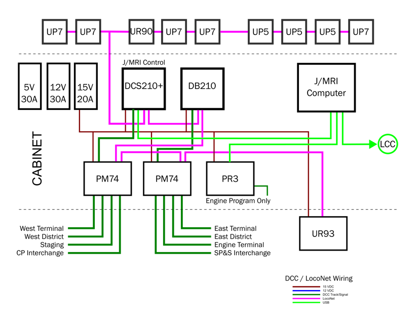
I have used the Digitrax DCC system since 2001, originally starting with a Super Chief system. My current configuration consists of a 15V 20A switching power supply, a DCS-210+ command station, a DB210 Booster, two PM-74 Power Managers, a UR-93 wireless throttle module, and a PR3 USB interface. There are nine UP-series panels around the layout, a UR-90, 3 UP-5 and 5 UP-7 modules. Most of the equipment is mounted in a cabinet, along with an additional 15VDC power supply to charge the throttles, a 12V 30A supply for turnout servos, and a 5V 20A supply for lighting and other electronics. I have two Buck Converters that reduce the 5V to 2.8V to directly drive most LED lighting on the layout. Several of the LCC nodes are also mounted in this cabinet, although most nodes for detection and turnout control are distributed around the layout.
There are 4 Digitrax throttles - two DT-600 and two UT-600 - all are radio equipped. I designed a holder with an integrated power plug. I simply drop the throttle into the holder and the power plug makes the connection so the throttles can be charged. You do need to select charge mode on the throttle after making the connection.
 Electronic Cabinet Overview
All of my engines are DCC + Sound equipped, and most are Tsunami brand. There are a few OEM modules as well, and all have been programmed for similar sound levels.
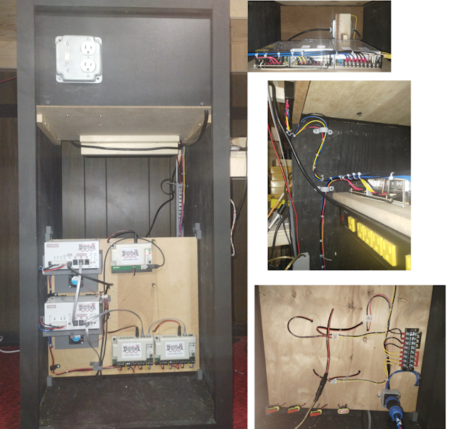
The outputs of the Power Managers are routed through 4-pin connectors so the entire DCC panel can be removed for service on the bench. I designed and 3D printed mounts for the 200-series command station and booster with an integrated cooling fan. The photo set on the right shows the cabinet with the removable DCC panel and a rear view showing the power supplies, power strip, and rear of the DCC panel.
Wiring
 Power Zone Distribution Panel
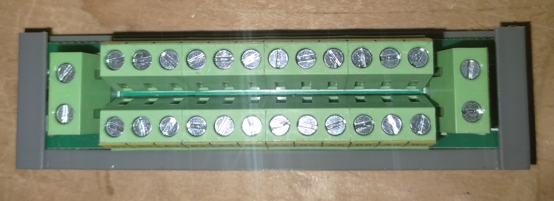
I use 14-gauge flexible wire as my main feed buss from the PM74 connectors to zone distribution panels located under the layout. These slide into 3D printed mounts to make connection easy without crawling under the table. I found that outdoor low-voltage wire was the lowest cost option, was easy to solder (provide solid connections in the distribution panels), and had proven insulation-displacement connectors for tapping into the line. I use these Power Zone Distribution Panels from Amazon - they provide a common A-B connection and 12 sub-connections. They can be daisy-chained, but so far 12 ports have been sufficient for my needs. The secondary ports connect to the track with an 18-gauge Red-Black 2 conductor cable. Red connects to "A" and black connect to "B". The 16g red wire passes through a detection coil before heading along a block. 22-gauge feeders from the rails connect to this 18g wire every 6 feet. This feed is usually between two pieces of flex-track, so a single feed provides power for 3-feet in either direction. The diagram below illustrates the connection of main buss, track block feed, and rail feed connections.
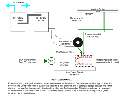 Power District Wiring
Since the LV lighting cable is black, I 3D printed wire identification tabs that connect with small nylon cable ties. These have a round area with "DCC", "LCC", "12V", or "5V" printed on them, plus a flat space where further identification can be written with a Sharpie marker. I do follow a consistent color-code for wiring:
- Black 14g 2-conductor - DCC Zone Feed Bus, one per power zone distribution panel.
- Red/Black 16g 2-conductor - DCC track block feed, one per detection block
- Red/Black 14g single conductors - 5V DC / Ground
- Yellow/Black 14g single conductors - 12V DC / Ground
- Blue/Black 14g single conductors - 15V DC/Ground
All of the wire is stranded for flexibility. I use 22g solid wire for the feed from the rails to the track block feed. I use PVC Pipe Clamps in 2, 1.5, and 1 inch sizes to route my cables below the layout, along with a variety of 3D printed clamps, holders, and clips for cable ties.
LCC
Still a work in progress!