Planning the Layout
I had several ideas in mind for my "dream" layout and did my best to include as many of those goals as possible. They included:
- Point to Point operation representing a division of a major railroad, with a cutoff to allow continuous running for display.
- A yard/terminal at each end of the division.
- An engine service facility with roundhouse and turntable; service facilities for both steam and diesel.
- A staging/storage yard to hold 3-5 medium length trains.
- Industries that "feed" each other, focusing on grain, fruit, and fuel/coal.
- Interchange with other roads, creating "micro-layouts" within the main layout.
- Open operation space, high level benchwork (chest height), minimal duck-under access.
- Use of electronics for train control, signaling, and automation.
- Space for the crew to relax before and after operating sessions, and a space for servicing cars and engines. A dedicated dispatcher station was desirable.
The design has captured each of these goals with minimal compromises.
The Available Space
The room chosen was 16 by 30 feet in size and at the base of the stairs to the basement. The room was finish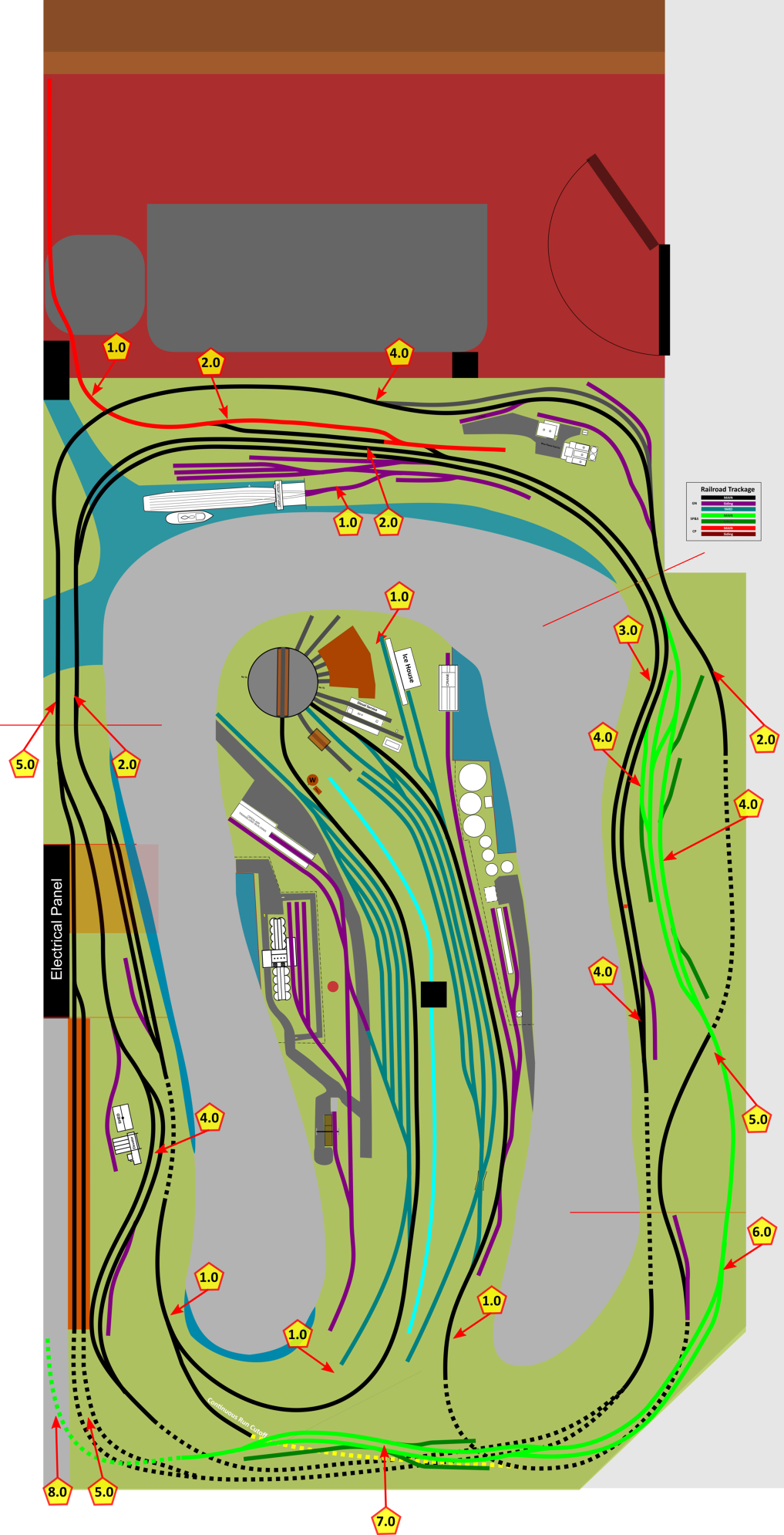 ed, had a small closet, but was open to the stairs. Since we often foster cats, I preferred an enclosed room to control access. The first order of business was to frame a small L-shaped wall and enclose the open side of the stairs. I cut an opening into the wall at the base of the stairs into the closet, creating a "cat-lock" entry. The crew passes through the closet into the train room, and the closet holds track and turnouts waiting for installation. This can later become an isolated room for a remote dispatcher once construction is complete.
We brought in a small couch and moved the train items into the lounge area - there are 4 open shelves with cabinets along the wall. The cabinets are perfect for displaying trains and memorabilia, and the cabinets are full of boxes of railcars, structures, and parts. One of the shelf areas is set up as a small workbench. This left 24 feet of the room for the layout, most of which was a bit over 16 feet wide with a small area with a 15-foot width.
Lighting
Before any work was done in the layout space, I removed the four incandescent light fixtures from the ceiling and installed 22 LED lights, replacing the ceiling tiles in the process. The lights allowed me to select 3K (warm white), 4.5K (daylight), or 6K (cool white). I selected the 4.5K option and wired all of them to an LED-compliant dimmer. I also added tiny spotlights in the lounge area to light up the display shelves.
Computer-Based Design
I used InkScape to sketch out the room space because it lets me create a "paper" of unlimited size and I can work in real measurements. I created the walls, support columns, electric panel, and any other areas that would require unusual or special access. I'm a big fan of "layout bashing" and using "Layout Design Elements" (LDEs) so I reviewed the layouts that had caught my interest over the years and scanned them. I could then bring in the layout or parts of the layout and see if the design could fit. Of course, the computer lets you rotate and flip things around. I then traced over these images using lines the same width as track. The images could then be removed, and I set to joining these LDEs together. I then spread this out to form the edges of the benchwork and used circle objects the size of an adult to make sure that the aisles were wide enough. The next step added "arms" to these circles that I could position at the edge of the aisle and determine the maximum comfortable reach. This set the depth for any main or yard track. The result is shown here on the right.
Evolution
This design helped to ensure that all turnouts were accessible for maintenance, that heights between track levels were sufficient, and the structure kits that I had been collecting for years would fit in the intended spaces. I have just two places with concerns. The hidden storage track below and the tail of the SP&S "micro-layout" are just beyond maximum reach in the bottom-left corner. I've come up with a way to make the SP&S level of track lift off in 3 sections should the track hidden below it require service. Likewise, there is a lift-out panel in front of the electric service panel that allows unfettered access to the panel. The panel's electronics are attached through a 9-conductor locking disconnect plug. This carries 2 DCC power districts and a turnout control, with two spare pins.
The actual design was recreated in AnyRail, which confirmed the curvatures and fitment of the turnouts, making a few minor adjustments. I'll show the AnyRail plan in the next installment, but for now point out two design changes. First, the staging tracks shown with a reddish-brown background were intended to be a "vertical switch" that moved an entire train down to a 4-track staging yard. The complexity of the rails and linear actuator placed below the layout was eliminated, replaced with a simple 4-track/2 track design on the main level. Secondly, after mentally routing cars, accessing the caboose track, and the engine terminal in the West yard, I added a runaround track to the ladder.