Planning for Growth
My new layout is a moderate size, wrapping around the walls in a 16x24-foot space. A peninsula extends into the center of the room. The design is point to point, with the East and West ends residing on opposite sides of the peninsula. The mainline runs around the room twice for about 160 feet of mainline run. I have an engine terminal, 2 yards, two interchanges with other railroads, and 4 staging tracks. There is enough space and track to keep four operators busy. All of my engines are sound-equipped, and moderate length freights will have two or 3 engines in a consist. With two yard and two mainline operators, up to 8 engines could be running at the same time.
This information directly drives the planning of the DCC system and wiring. Using an average of 0.75A per active engine means that at least 6 amps of power are required. Some of the older brass engines will draw more power, so an 8A system was selected and a Digitrax DCS210+ was purchased. This came with a 5A power supply and a DT602 throttle. 
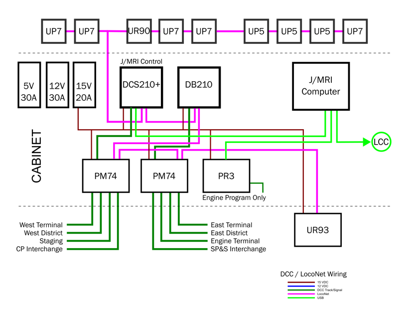
I then started to think about how and where trains would operate and started breaking the layout into "power districts". A power district basically allows you to deliver power to a section of your layout through a circuit breaker. If a derailment occurs and results in a short-circuit, only that section of the layout would be affected. I divided the layout into power districts based on the two yards, the engine terminal, the two mainline loops, the staging yard, and each of the two "mini-layouts" representing the interchange railroads - eight districts in total. I used a pair of Digitrax PM74s to create the eight power districts. After discussing operational planning with some fellow railroaders and potential operators, I decided to increase the current capacity to the layout by adding a DB210 booster. The command station now fed one of the PM74s and the booster fed the other. I used a 15V 20A switching power supply to feed both the command station and booster, which allowed 4A of headroom. Another 0.5A of the 15V supply will drive the powered modules such as the PM74s, the UR93, and the PR3. Most of these devices are mounted on a removable panel in a small cabinet under the layout. There is a shelf with the 3 power supplies (15V, 12V and 5V), a panel for DCC, and a panel for LCC. All of the devices on these panels benefit from a central location. Other LCC devices are distributed around the layout to minimize wiring, but that will be discussed in another installment. The diagram to the right shows the major parts of the DCC system and the devices located in the cabinet vs. out on the layout.
Planning for Operation
With a walk-around format, I wanted to have enough locations to connect tethered throttles. I planned for using Duplex radio throttles, but batteries don't have infinite life! Being able to connect to the LocoNet bus while operating was a core requirement. I placed a UP panel every 6 to 8 feet for a total 9 panels. There is a UR90 for IR connections, three UP5 and five UP7 panels. These are mounted in 3D printed frames just below the fascia. (see the Store page for free STL files!) The UR93 radio transceiver is mounted to a drop-ceiling crossmember near the center of the layout for optimal coverage.
Having enough power is just part of the goal. That power needs to reach the rails reliably. I mostly use flex track but have some 36" lengths of hand-laid track. I solder two sections together and place a feed at the center of each 6-foot section. There are rail joiners at each joint but the 6-foot sections don't depend on their connectivity for power! A 14-gauge wire is routed from the central cabinet to "distribution blocks" around the layout. I found that the low-voltage wire used for outdoor lighting was economical and the stranded wire was easier to work with than solid Romex type cable. Lighter, 18-gauge wires run from this block to the track connections, which are made from 22-gauge 2-conductor solid wire. The 18-gauge wire passes through a detection coil and powers multiple segments of a single signaling block.
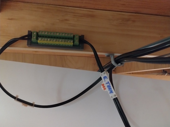
The photo shows the 14-gauge wires connecting to the distribution block. This 12-pair block is modified by cutting the traces to create two 6-pair sections. Also shown in the photo are the 3D printed tags that identify the major wires under the layout and behind the electronics cabinet. I created these tags with a small half-circle with "DCC", "LCC", "12V", and "5V" raised text that identifies the purpose of the cable. The large flat section allows writing of the endpoint - these route to the peninsula that serves the East and West Terminal power districts. The distribution block slips into a 3D printed mount that allows easier access and manipulation of the connections.
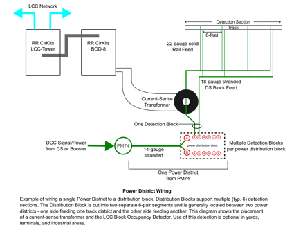
The schematic on the right shows how this is wired, including how the detection circuit is deployed. While this shows an LCC-based detection, the concept applies to any method of detecting block occupancy by sensing current draw.
You can also see how one power district feeds up to six detection blocks, and a detection section main cable follows the track and delivers many small-gauge feeder wires to the track.
If a power district has more than 6 detection blocks, I run a separate 14-gauge primary feed to another distribution terminal block.
Special Considerations - Grade Crossings and Reversing Sections
So far, the wiring and support for detection is primarily for signaling, but what about grade crossings? The detection circuit that I use has 8 sections. These are usually located next to the distribution terminal block and only 6 are used. To address a grade crossing, I splice a detection section feed wire immediately after the current sense transformer. That wire is passed through a second current sense transformer and routed to a block that covers the crossing area. The first coil handles signaling while the second coil feeds the small sub-section to trigger the crossing logic.
My layout is point to point, with both East and West points residing on opposite sides of a peninsula. There's a shared engine terminal at the end of the peninsula (modelers license # 193235). The "A" rail always faces the aisle so when the tracks approach the turntable, the East approach track is reversed from the West approach and the roundhouse stalls. The turntable is a Walthers model that contains auto-reversing logic, so I don't need to worry about that. I also don't need to worry about train length in the reversing section as I can fit at most two diesels on the turntable. I handled this by isolating the East approach track and wiring the feed to that track through an auto-reverse module. The track feed from the distribution terminal block is wired into the A-R, and the output of the A-R feeds the 30" section of approach track directly with 22-gauge feed wire. These connections are all relatively short - 18-24 inches - and only need to carry current for one or two engines across the turntable and into the stalls
Update - After wiring this section and filling the roundhouse with engines, the cacophony of steam and diesel engines idling was a bit overwhelming. I created a small panel that could selectively remove power from the 7 stalls and storage tracks. This reduces power draw as well as the sound level.
Summary
This wraps up the planning of the DCC subsystem, including decisions on where to locate the controller, wire gauges, and components used to feed the track sections. The planning - notes and creating the schematic diagrams in this article - are part of the documentation that will be used to maintain the layout.