Recap
So far, we have obtained a suitable body for the project, stripped the old paint, and decided on the paint scheme. We'll next look at preparing the body, deciding what details to add, and how to power the engine.
Before moving forward, I collected several photos of the prototype engine and reviewed the details with Spencer. I ordered brass wire to form the handrails, horns, and eye ring bolts, plus a set of 40" wheel sets. Knowing it would take a few days for them to be delivered, I set upon preparing the body and planning the new chassis.
Body Prep
The first thing we needed to do was to examine the body for defects. The large holes in the roof from the original horn and the slots in the body from mounting the trucks needed to be filled. I used Tamiya putty, pushing it through from the inside of the body. After allowing the putty to dry for 24-hours, the body was sanded and polished with progressively finer sanding sticks, starting with 220 grit and finishing with 800 grit. Some parts of the nose were crazed from a previous heavy application of paint, so these areas were also polished to minimize the damage.
Looking at prototype photos showed that the battery box and fuel tank indicator were set back from the body by about 2 inches. I cut these from the body, filed the edges smooth and set them aside. These would be affixed directly to the chassis to provide the necessary set-back.
Handrails and Grabs
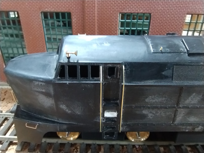
The next step was to locate the position for handrails and grab irons, based on prototype photos. I used a #17 chisel blade in a handle to remove the cast-on handrails and grabs. The body was then polished with sanding sticks to remove any trace of the original grabs. The start and end points of the grabs were then marked with a needle awl, creating small dimples. To add additional grabs not on the original body, I used a known object's size to set the scale of an image to approximately HO scale. It was then a trivial task to measure that distance and transfer it to the model, again marking the points with the needle awl. Once all of the positions were marked, I began drilling the holes for the handrails, grabs, and the horn. 
I used to use a pin vise to drill the holes, but this method now causes my hands to cramp, so I found a new method. A Dremel is too fast to get an accurate start without mounting it in a stand, so I purchased a surplus Pet Claw Trimmer (guaranteed dead batteries!) from American Scientific and Surplus. This was a variable speed, lightweight motor tool with a 1/8" chuck. I hard-wired a small 12VDC power supply into this tool, and at slow speed, I can prevent the tool from turning. This allows me to set the bit at the dimple and slowly release the finger pressure on the chuck. The holes are drilled quickly, and the bit doesn't wander off the mark. Another benefit is that the chuck from my pin vise is an exact match, allowing me to use any size micro-bit.
Once the holes were drilled, Tichy grab irons were installed and secured with medium CA. After allowing the glue to set for a few minutes, I started forming the handrails for the cab, nose, rear door, and rear sides. I used 0.015" brass wire, which scales to about 1" diameter. I again used medium thickness CA on the wire - applying a dab to the wire with a toothpick and then pressing them the rest of the way into the holes.
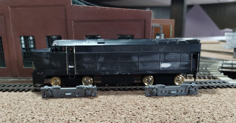
The two photos show the placement of the grabs and handrails, as well as the body set onto the chassis and dummy trucks. The original sideframes are shown in the approximate position. The model trucks are about 11" oversize for the prototype 9-foot 10-inch wheelbase. This wheelbase isn't available so we will be adjusting this to a standard 10-foot wheelbase.
Other Details
A pair of single-chime horns were added over the cab. These were installed by drilling appropriately sized holes and securing the horn with medium CA. I 3D-printed two additional details for the model - the lift-ring bar that sits above the rear door and the backup light that mounts just to the right of the rear door, about level with the window. These were printed on an FDM printer with a 0.2mm head. These were glued into place with plastic cement.
Chassis and Trucks
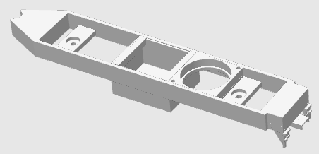
Since the original mounting holes were filled  in, I decided to create a 3D-printed chassis that integrated the two truck bolsters, the weight area in the fuel tank, a speaker box, and the rear coupler box and MU brackets. The chassis will be printed in matte black PLA+ filament. The bolsters have recessed areas to secure the threaded shaft that rises from the trucks, secured with two nuts. The fuel tank was narrowed slightly to match the prototype inset from the body side. All but one of the original steel weights fit into this modified size, and the additional weight can be secured to the top of the stack. The speaker enclosure is sized for a 1-inch round speaker that faces down, and a vented cover snaps in place. The rear coupler box is sized for a Kadee #5 coupler, with the cover attached with a single 2-56 screw. The chassis is a snug friction fit into the body.
Trucks were printed in 3 pieces - the body, axle cover. and the bolster plate. A 3/4" long 2-56 cap-head screw is passed through the hole in the bolster plate and secured with epoxy. This mirrors the truck attachment method of the NWSL Stanton drive unit, allowing the dummy truck and the Stanton drive to be easily exchanged. The bolster plate is glued to the top-center of the truck body once the epoxy has set. The 40" brass wheelsets are placed into the body and secured with the axle cover plate. The plate snaps into place and can be secured with a pair of 2-56 coarse thread screws.
Lighting
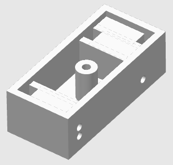
 The model had a single bulb that lit the cab, headlight, class lights, and much of the ground below the engine! Since the class lights were simply framed holes in the nose, it was a trivial task to install fiber-optic filament to provide more realistic lighting. The lighting box has 3 sections where LEDs can be inserted. The wires pass through a small hole in the bottom of the box. The Fiber Optic filaments are inserted into the holes on the side of the box - two for the class lights and one each for the headlight and backup light. The filament passes through the solid section to ensure that the fiber is aligned with the LED. The class light cavity supports the use of two micro-LEDs in white and green, while the headlight and backup light utilize a single white LED. The box is secured to the underside of the body roof with double-sided foam tape. The LED wires are connected using 5 wires of a six-pin micro connector. Filaments are a press-fit, allowing future serviceability. The cover has a recessed portion to ensure that no light can pass through the box to other elements or into the body. The original headlight lens was drilled to allow the fiber-optic filament to be inserted. The ends of the filaments were polished by dipping them into MEK and allowed to air dry.
Summary
The model has all of the details attached, the 3D printed trucks and chassis have been tested and verified against the NWSL Stanton drive. I gave the model a gentle wash with Dawn dish detergent and a thorough rinse before allowing it 24-hours to air-dry. It's now in the paint booth awaiting its next steps!